Chip Interfaces, Implementations, Schematics
Given / Primitive (2 Gates)
- Nand
- DFF
Provided (5 Chips)
ARegister
/**
 * A 16-Bit register called "A Register".
 * If load[t-1]=1 then out[t] = in[t-1]
 * else out does not change (out[t] = out[t-1])
 *
 * This built-in chip implementation has the side effect of
 * providing a GUI representation of a 16-bit register
 * called "A register" (typically used to store an address).
 */

CHIP ARegister {

    IN  in[16], load;
    OUT out[16];

    BUILTIN ARegister;
    CLOCKED in, load;
}
DRegister
/**
 * A 16-Bit register called "D Register".
 * If load[t-1]=1 then out[t] = in[t-1]
 * else out does not change (out[t] = out[t-1])
 *
 * This built-in chip implementation has the side effect of
 * providing a GUI representation of a 16-bit register
 * called "D register" (typically used to store data).
 */

CHIP DRegister {

    IN  in[16], load;
    OUT out[16];

    BUILTIN DRegister;
    CLOCKED in, load;
}
ROM32K
/**
 * Read-Only memory (ROM) of 16K registers, each 16-bit wide.
 * The chip is designed to facilitate data read, as follows:
 *     out(t) = ROM32K[address(t)](t)
 * In words: the chip always outputs the value stored at the
 * memory location specified by address.
 *
 * The built-in chip implementation has a GUI side-effect,
 * showing an array-like component that displays the ROM's
 * contents. The ROM32K chip is supposed to be pre-loaded with
 * a machine language program. To that end, the built-in chip
 * implementation also knows how to handle the "ROM32K load Xxx"
 * script command, where Xxx is the name of a text file containing
 * a program written in the Hack machine language.  When the
 * simulator encounters such a command in a test script, the code
 * found in the file is loaded into the simulated ROM32K unit.
 */

CHIP ROM32K {

    IN  address[15];
    OUT out[16];

    BUILTIN ROM32K;
}
Screen
/**
 * The Screen (memory map).
 * Functions exactly like a 16-bit 8K RAM:
 *    1. out(t)=Screen[address(t)](t)
 *    2. If load(t-1) then Screen[address(t-1)](t)=in(t-1)
 *
 * The built-in chip implementation has the side effect of continuously
 * refreshing a visual 256 by 512 black-and-white screen, simulated
 * by the simulator. Each row in the visual screen is represented
 * by 32 consecutive 16-bit words, starting at the top left corner
 * of the visual screen. Thus the pixel at row r from the top and
 * column c from the left (0<=r<=255, 0<=c<=511) reflects the c%16
 * bit (counting from LSB to MSB) of the word found in
 * Screen[r*32+c/16].
 */

CHIP Screen {

    IN  in[16],    // what to write
    load,          // write-enable bit
    address[13];   // where to read/write
    OUT out[16];   // Screen value at the given address

    BUILTIN Screen;
    CLOCKED in, load;
}
Keyboard
/**
 * The keyboard (memory map).
 * Outputs the code of the currently pressed key.
 *
 * The built-in chip implementation has two side effects supplied
 * by the simulator. First, the keyboard memory map is continuously
 * being refreshed from the physical keyboard unit. Second, it
 * displays a keyboard icon and data entry GUI.
 */

CHIP Keyboard {

    OUT out[16];   // The ASCII code of the pressed key,
                   // or 0 if no key is currently pressed,
                   // or one the special codes listed in Figure 5.5.

    BUILTIN Keyboard;
}
Boolean Logic (15 Gates)
Not
/**
 * Not gate:
 * out = not in
 */

CHIP Not {
    IN in;
    OUT out;

    PARTS:
    Nand (a=in, b=in, out=out);
}
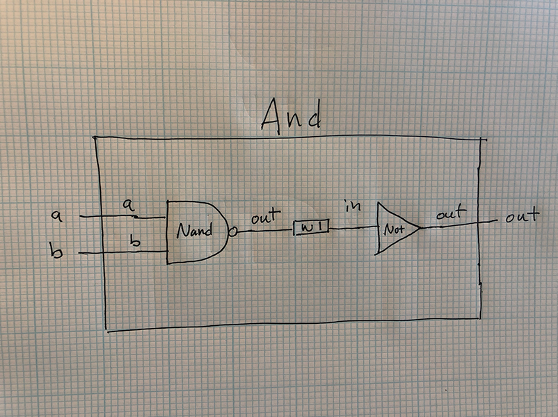
And
/**
 * And gate:
 * out = 1 if (a == 1 and b == 1)
 *       0 otherwise
 */

CHIP And {
    IN a, b;
    OUT out;

    PARTS:
    Nand (a=a, b=b, out=w1);
    Not (in=w1, out=out);
}
Or
/**
 * Or gate:
 * out = 1 if (a == 1 or b == 1)
 *       0 otherwise
 */

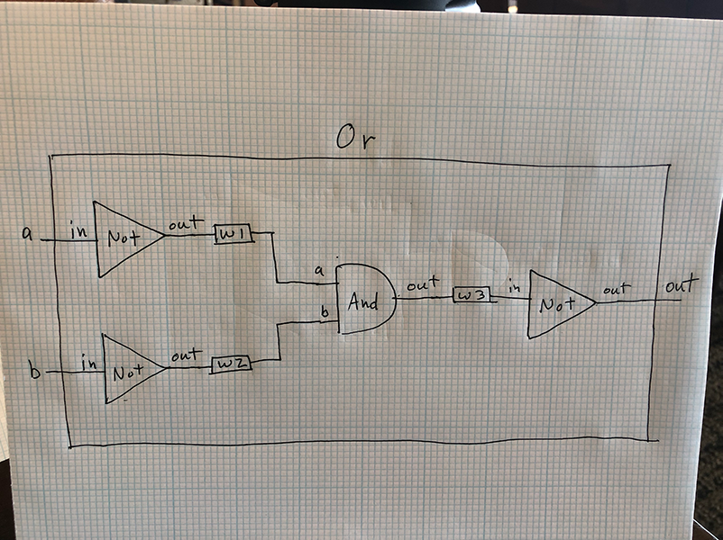
CHIP Or {
    IN a, b;
    OUT out;

    PARTS:
    Not (in=a, out=w1);
    Not (in=b, out=w2);
    And (a=w1, b=w2, out=w3);
    Not (in=w3, out=out);
}
Xor
/**
 * Exclusive-or gate:
 * out = not (a == b)
 */

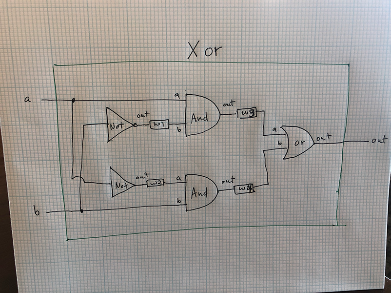
CHIP Xor {
    IN a, b;
    OUT out;

    PARTS:
    Not (in=b, out=w1);
    Not (in=a, out=w2);
    And (a=a, b=w1, out=w3);
    And (b=b, a=w2, out=w4);
    Or (a=w3, b=w4, out=out);
}
Mux
/**
 * Multiplexor:
 * out = a if sel == 0
 *       b otherwise
 */

CHIP Mux {
    IN a, b, sel;
    OUT out;

    PARTS:
    // Inverted DMux
    Not (in=sel, out=w1);
    And (a=a, b=w1, out=w2);
    And (a=sel, b=b, out=w3);
    Or (a=w2, b=w3, out=out);
}
DMux
/**
 * Demultiplexor:
 * {a, b} = {in, 0} if sel == 0
 *          {0, in} if sel == 1
 */

// API
// DMux(in= ,sel= ,a= ,b= );

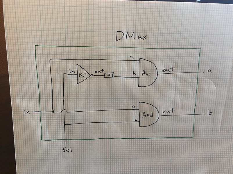
CHIP DMux {
    IN in, sel;
    OUT a, b;

    PARTS:
    Not (in=sel, out=w1);
    And (a=in, b=w1, out=a);
    And (a=in, b=sel, out=b);
}
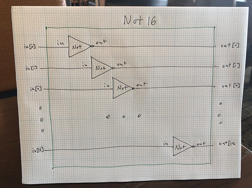
Not16
CHIP Not16 {
    IN in[16];
    OUT out[16];

    PARTS:
    Not (in=in[0], out=out[0]);
    Not (in=in[1], out=out[1]);
    Not (in=in[2], out=out[2]);
    Not (in=in[3], out=out[3]);
    Not (in=in[4], out=out[4]);
    Not (in=in[5], out=out[5]);
    Not (in=in[6], out=out[6]);
    Not (in=in[7], out=out[7]);
    Not (in=in[8], out=out[8]);
    Not (in=in[9], out=out[9]);
    Not (in=in[10], out=out[10]);
    Not (in=in[11], out=out[11]);
    Not (in=in[12], out=out[12]);
    Not (in=in[13], out=out[13]);
    Not (in=in[14], out=out[14]);
    Not (in=in[15], out=out[15]);
}
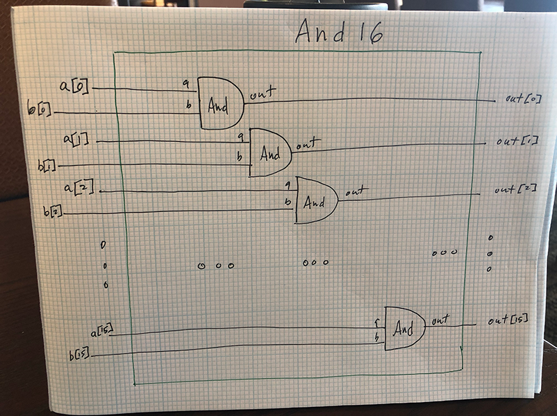
And16
/**
 * 16-bit Not:
 * for i=0..15: out[i] = not in[i]
 */

CHIP Not16 {
    IN in[16];
    OUT out[16];

    PARTS:
    Not (in=in[0], out=out[0]);
    Not (in=in[1], out=out[1]);
    Not (in=in[2], out=out[2]);
    Not (in=in[3], out=out[3]);
    Not (in=in[4], out=out[4]);
    Not (in=in[5], out=out[5]);
    Not (in=in[6], out=out[6]);
    Not (in=in[7], out=out[7]);
    Not (in=in[8], out=out[8]);
    Not (in=in[9], out=out[9]);
    Not (in=in[10], out=out[10]);
    Not (in=in[11], out=out[11]);
    Not (in=in[12], out=out[12]);
    Not (in=in[13], out=out[13]);
    Not (in=in[14], out=out[14]);
    Not (in=in[15], out=out[15]);
}
Or16
/**
 * 16-bit bitwise Or:
 * for i = 0..15 out[i] = (a[i] or b[i])
 */

CHIP Or16 {
    IN a[16], b[16];
    OUT out[16];

    PARTS:
    Or (a=a[0], b=b[0], out=out[0]);
    Or (a=a[1], b=b[1], out=out[1]);
    Or (a=a[2], b=b[2], out=out[2]);
    Or (a=a[3], b=b[3], out=out[3]);
    Or (a=a[4], b=b[4], out=out[4]);
    Or (a=a[5], b=b[5], out=out[5]);
    Or (a=a[6], b=b[6], out=out[6]);
    Or (a=a[7], b=b[7], out=out[7]);
    Or (a=a[8], b=b[8], out=out[8]);
    Or (a=a[9], b=b[9], out=out[9]);
    Or (a=a[10], b=b[10], out=out[10]);
    Or (a=a[11], b=b[11], out=out[11]);
    Or (a=a[12], b=b[12], out=out[12]);
    Or (a=a[13], b=b[13], out=out[13]);
    Or (a=a[14], b=b[14], out=out[14]);
    Or (a=a[15], b=b[15], out=out[15]);
}
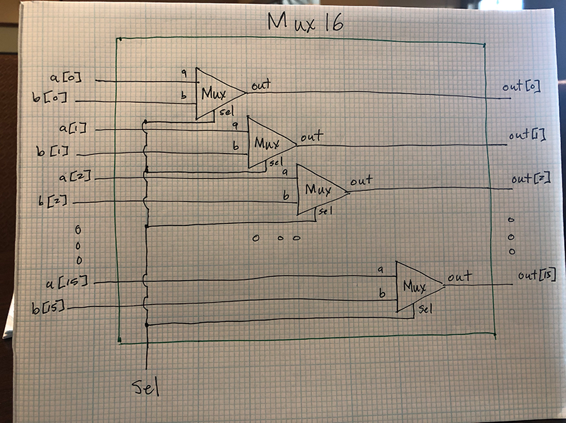
Mux16
/**
 * 16-bit multiplexor:
 * for i = 0..15 out[i] = a[i] if sel == 0
 *                        b[i] if sel == 1
 */

CHIP Mux16 {
    IN a[16], b[16], sel;
    OUT out[16];

    PARTS:
    Mux (a=a[0], b=b[0], sel=sel, out=out[0]);
    Mux (a=a[1], b=b[1], sel=sel, out=out[1]);
    Mux (a=a[2], b=b[2], sel=sel, out=out[2]);
    Mux (a=a[3], b=b[3], sel=sel, out=out[3]);
    Mux (a=a[4], b=b[4], sel=sel, out=out[4]);
    Mux (a=a[5], b=b[5], sel=sel, out=out[5]);
    Mux (a=a[6], b=b[6], sel=sel, out=out[6]);
    Mux (a=a[7], b=b[7], sel=sel, out=out[7]);
    Mux (a=a[8], b=b[8], sel=sel, out=out[8]);
    Mux (a=a[9], b=b[9], sel=sel, out=out[9]);
    Mux (a=a[10], b=b[10], sel=sel, out=out[10]);
    Mux (a=a[11], b=b[11], sel=sel, out=out[11]);
    Mux (a=a[12], b=b[12], sel=sel, out=out[12]);
    Mux (a=a[13], b=b[13], sel=sel, out=out[13]);
    Mux (a=a[14], b=b[14], sel=sel, out=out[14]);
    Mux (a=a[15], b=b[15], sel=sel, out=out[15]);
}
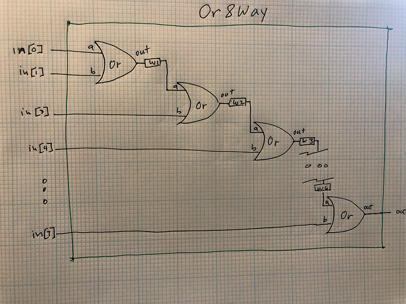
Or8Way
/**
 * 8-way Or:
 * out = (in[0] or in[1] or ... or in[7])
 */

CHIP Or8Way {
    IN in[8];
    OUT out;

    PARTS:
    Or (a=in[0], b=in[1], out=w1);
    Or (a=w1, b=in[2], out=w2);
    Or (a=w2, b=in[3], out=w3);
    Or (a=w3, b=in[4], out=w4);
    Or (a=w4, b=in[5], out=w5);
    Or (a=w5, b=in[6], out=w6);
    Or (a=w6, b=in[7], out=out);
}
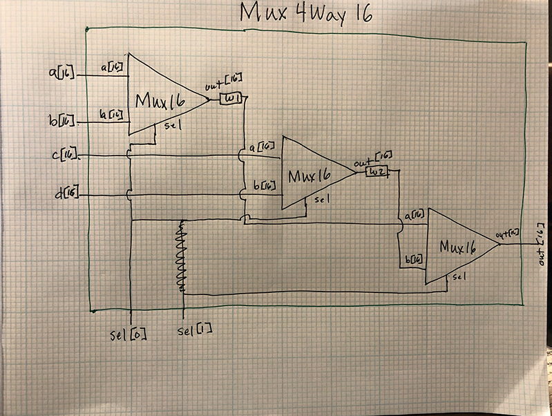
Mux4Way16
/**
 * 4-way 16-bit multiplexor:
 * out = a if sel == 00
 *       b if sel == 01
 *       c if sel == 10
 *       d if sel == 11
 */

CHIP Mux4Way16 {
    IN a[16], b[16], c[16], d[16], sel[2];
    OUT out[16];

    PARTS:
    Mux16 (a=a, b=b, sel=sel[0], out=w1);
    Mux16 (a=c, b=d, sel=sel[0], out=w2);
    Mux16 (a=w1, b=w2, sel=sel[1], out=out);
}
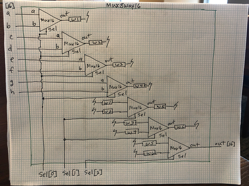
Mux8Way16
/**
 * 8-way 16-bit multiplexor:
 * out = a if sel == 000
 *       b if sel == 001
 *       etc.
 *       h if sel == 111
 */

CHIP Mux8Way16 {
    IN a[16], b[16], c[16], d[16],
       e[16], f[16], g[16], h[16],
       sel[3];
    OUT out[16];

    PARTS:
    Mux16 (a=a, b=b, sel=sel[0], out=w1);
    Mux16 (a=c, b=d, sel=sel[0], out=w2);
    Mux16 (a=e, b=f, sel=sel[0], out=w3);
    Mux16 (a=g, b=h, sel=sel[0], out=w4);
    Mux16 (a=w1, b=w2, sel=sel[1], out=w5);
    Mux16 (a=w3, b=w4, sel=sel[1], out=w6);
    Mux16 (a=w5, b=w6, sel=sel[2], out=out);
}
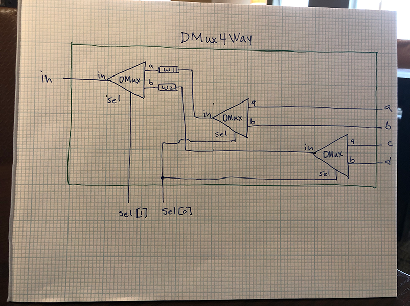
DMux4Way
/**
 * 4-way demultiplexor:
 * {a, b, c, d} = {in, 0, 0, 0} if sel == 00
 *                {0, in, 0, 0} if sel == 01
 *                {0, 0, in, 0} if sel == 10
 *                {0, 0, 0, in} if sel == 11
 */

CHIP DMux4Way {
    IN in, sel[2];
    OUT a, b, c, d;

    PARTS:
    DMux (in=in, a=w1, b=w2, sel=sel[1]);
    DMux (in=w1, a=a, b=b, sel=sel[0]);
    DMux (in=w2, a=c, b=d, sel=sel[0]);
}
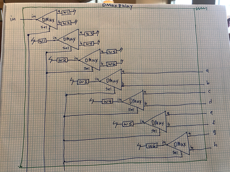
DMux8Way
/**
 * 8-way demultiplexor:
 * {a, b, c, d, e, f, g, h} = {in, 0, 0, 0, 0, 0, 0, 0} if sel == 000
 *                            {0, in, 0, 0, 0, 0, 0, 0} if sel == 001
 *                            etc.
 *                            {0, 0, 0, 0, 0, 0, 0, in} if sel == 111
 */

CHIP DMux8Way {
    IN in, sel[3];
    OUT a, b, c, d, e, f, g, h;

    PARTS:
    DMux (in=in, a=w1, b=w2, sel=sel[2]);
    DMux (in=w1, a=w3, b=w4, sel=sel[1]);
    DMux (in=w2, a=w5, b=w6, sel=sel[1]);
    DMux (in=w3, a=a, b=b, sel=sel[0]);
    DMux (in=w4, a=c, b=d, sel=sel[0]);
    DMux (in=w5, a=e, b=f, sel=sel[0]);
    DMux (in=w6, a=g, b=h, sel=sel[0]);
}
Boolean Arithmetic (5 Chips)
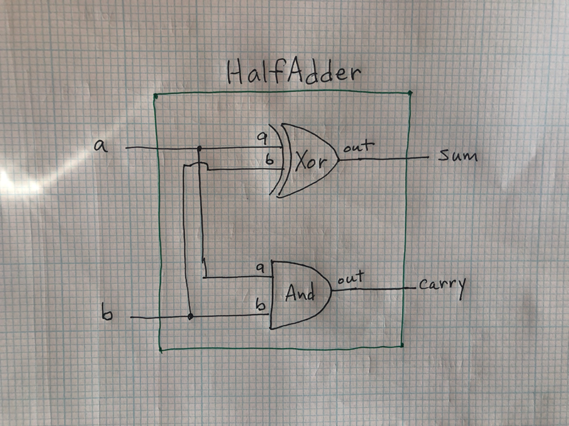
HalfAdder
/**
 * Computes the sum of two bits.
 */

CHIP HalfAdder {
    IN a, b;    // 1-bit inputs
    OUT sum,    // Right bit of a + b
        carry;  // Left bit of a + b

    PARTS:
    Xor(a=a, b=b, out=sum);
    And(a=a, b=b, out=carry);
}
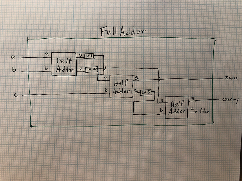
FullAdder
/**
 * Computes the sum of three bits.
 */

CHIP FullAdder {
    IN a, b, c;  // 1-bit inputs
    OUT sum,     // Right bit of a + b + c
        carry;   // Left bit of a + b + c

    PARTS:
    HalfAdder(a=a, b=b, sum=w1, carry=w2);
    HalfAdder(a=w1, b=c, sum=sum, carry=w3);
    HalfAdder(a=w2, b=w3, sum=carry, carry=false);
}
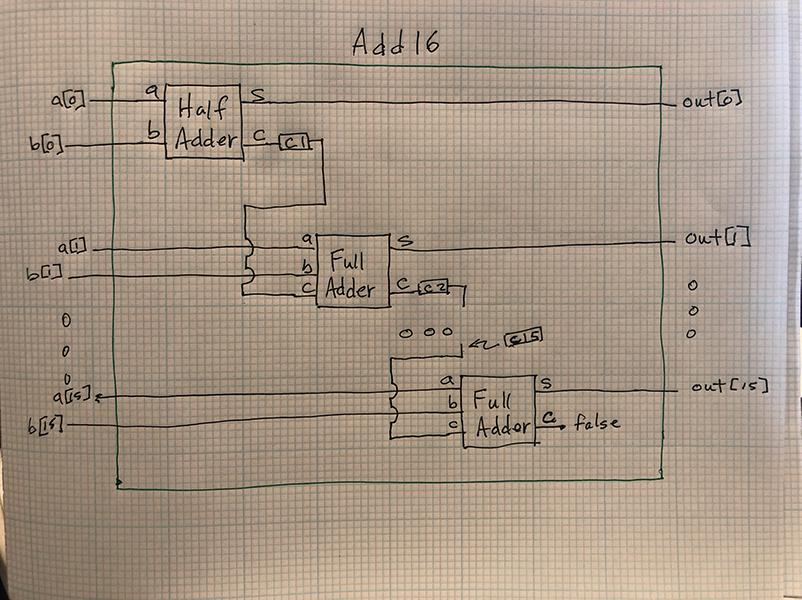
Add16
/**
 * Adds two 16-bit values.
 * The most significant carry bit is ignored.
 */


CHIP Add16 {
    IN a[16], b[16];
    OUT out[16];

    PARTS:
    HalfAdder(a=a[0], b=b[0], sum=out[0], carry=c1);
    FullAdder(a=a[1], b=b[1], c=c1, sum=out[1], carry=c2);
    FullAdder(a=a[2], b=b[2], c=c2, sum=out[2], carry=c3);
    FullAdder(a=a[3], b=b[3], c=c3, sum=out[3], carry=c4);
    FullAdder(a=a[4], b=b[4], c=c4, sum=out[4], carry=c5);
    FullAdder(a=a[5], b=b[5], c=c5, sum=out[5], carry=c6);
    FullAdder(a=a[6], b=b[6], c=c6, sum=out[6], carry=c7);
    FullAdder(a=a[7], b=b[7], c=c7, sum=out[7], carry=c8);
    FullAdder(a=a[8], b=b[8], c=c8, sum=out[8], carry=c9);
    FullAdder(a=a[9], b=b[9], c=c9, sum=out[9], carry=c10);
    FullAdder(a=a[10], b=b[10], c=c10, sum=out[10], carry=c11);
    FullAdder(a=a[11], b=b[11], c=c11, sum=out[11], carry=c12);
    FullAdder(a=a[12], b=b[12], c=c12, sum=out[12], carry=c13);
    FullAdder(a=a[13], b=b[13], c=c13, sum=out[13], carry=c14);
    FullAdder(a=a[14], b=b[14], c=c14, sum=out[14], carry=c15);
    FullAdder(a=a[15], b=b[15], c=c15, sum=out[15], carry=false);
}
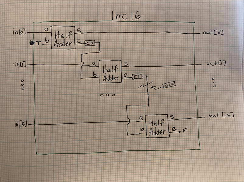
Inc16
/**
 * 16-bit incrementer:
 * out = in + 1 (arithmetic addition)
 */

CHIP Inc16 {
    IN in[16];
    OUT out[16];

    PARTS:
    HalfAdder(a=in[0], b=true, sum=out[0], carry=c0);
    HalfAdder(a=in[1], b=c0, sum=out[1], carry=c1);
    HalfAdder(a=in[2], b=c1, sum=out[2], carry=c2);
    HalfAdder(a=in[3], b=c2, sum=out[3], carry=c3);
    HalfAdder(a=in[4], b=c3, sum=out[4], carry=c4);
    HalfAdder(a=in[5], b=c4, sum=out[5], carry=c5);
    HalfAdder(a=in[6], b=c5, sum=out[6], carry=c6);
    HalfAdder(a=in[7], b=c6, sum=out[7], carry=c7);
    HalfAdder(a=in[8], b=c7, sum=out[8], carry=c8);
    HalfAdder(a=in[9], b=c8, sum=out[9], carry=c9);
    HalfAdder(a=in[10], b=c9, sum=out[10], carry=c10);
    HalfAdder(a=in[11], b=c10, sum=out[11], carry=c11);
    HalfAdder(a=in[12], b=c11, sum=out[12], carry=c12);
    HalfAdder(a=in[13], b=c12, sum=out[13], carry=c13);
    HalfAdder(a=in[14], b=c13, sum=out[14], carry=c14);
    HalfAdder(a=in[15], b=c14, sum=out[15], carry=false);
}
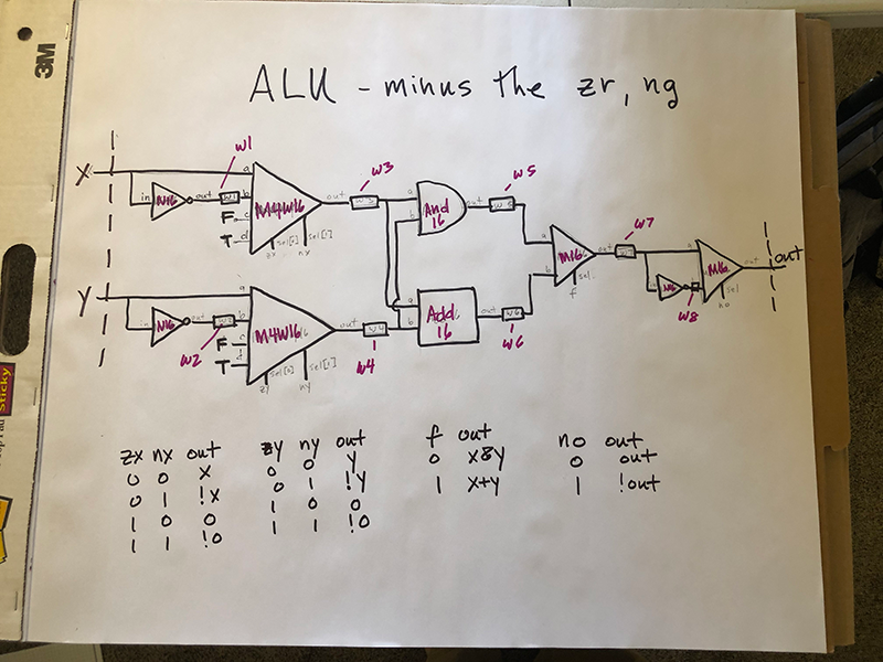
ALU
/**
 * The ALU (Arithmetic Logic Unit).
 * Computes one of the following functions:
 * x+y, x-y, y-x, 0, 1, -1, x, y, -x, -y, !x, !y,
 * x+1, y+1, x-1, y-1, x&y, x|y on two 16-bit inputs,
 * according to 6 input bits denoted zx,nx,zy,ny,f,no.
 * In addition, the ALU computes two 1-bit outputs:
 * if the ALU output == 0, zr is set to 1; otherwise zr is set to 0;
 * if the ALU output < 0, ng is set to 1; otherwise ng is set to 0.
 */

// Implementation: the ALU logic manipulates the x and y inputs
// and operates on the resulting values, as follows:
// if (zx == 1) set x = 0        // 16-bit constant
// if (nx == 1) set x = !x       // bitwise not
// if (zy == 1) set y = 0        // 16-bit constant
// if (ny == 1) set y = !y       // bitwise not
// if (f == 1)  set out = x + y  // integer 2's complement addition
// if (f == 0)  set out = x & y  // bitwise and
// if (no == 1) set out = !out   // bitwise not
// if (out == 0) set zr = 1
// if (out < 0) set ng = 1

CHIP ALU {
    IN
        x[16], y[16],  // 16-bit inputs
        zx, // zero the x input?
        nx, // negate the x input?
        zy, // zero the y input?
        ny, // negate the y input?
        f,  // compute out = x + y (if 1) or x & y (if 0)
        no; // negate the out output?

    OUT
        out[16], // 16-bit output
        zr, // 1 if (out == 0), 0 otherwise
        ng; // 1 if (out < 0),  0 otherwise

    PARTS:
        Not16(in=x, out=w1);
        Not16(in=y, out=w2);
        Mux4Way16(a=x, b=w1, c=false, d=true, sel[1]=zx, sel[0]=nx, out=w3);
        Mux4Way16(a=y, b=w2, c=false, d=true, sel[1]=zy, sel[0]=ny, out=w4);
        And16(a=w3, b=w4, out=w5);
        Add16(a=w3, b=w4, out=w6);
        Mux16(a=w5, b=w6, sel=f, out=w7);
        Not16(in=w7, out=w8);
        Mux16(a=w7,b=w8, sel=no, out=out, out[0]=out0, out[1]=out1, out[2]=out2, out[3]=out3, out[4]=out4, out[5]=out5, out[6]=out6, out[7]=out7, out[8]=out8, out[9]=out9, out[10]=out10, out[11]=out11, out[12]=out12, out[13]=out13, out[14]=out14, out[15]=out15, out[15]=ng);
        Or8Way(in[0]=out0, in[1]=out1, in[2]=out2, in[3]=out3, in[4]=out4, in[5]=out5, in[6]=out6, in[6]=out7, out=or8wayout0);
        Or8Way(in[0]=out8, in[1]=out9, in[2]=out10, in[3]=out11, in[4]=out12, in[5]=out13, in[6]=out14, in[6]=out15, out=or8wayout1);
        Or(a=or8wayout0, b=or8wayout1, out=orout);
        Not(in=orout, out=zr);
}


Sequential Logic (8 Gates / Chips)
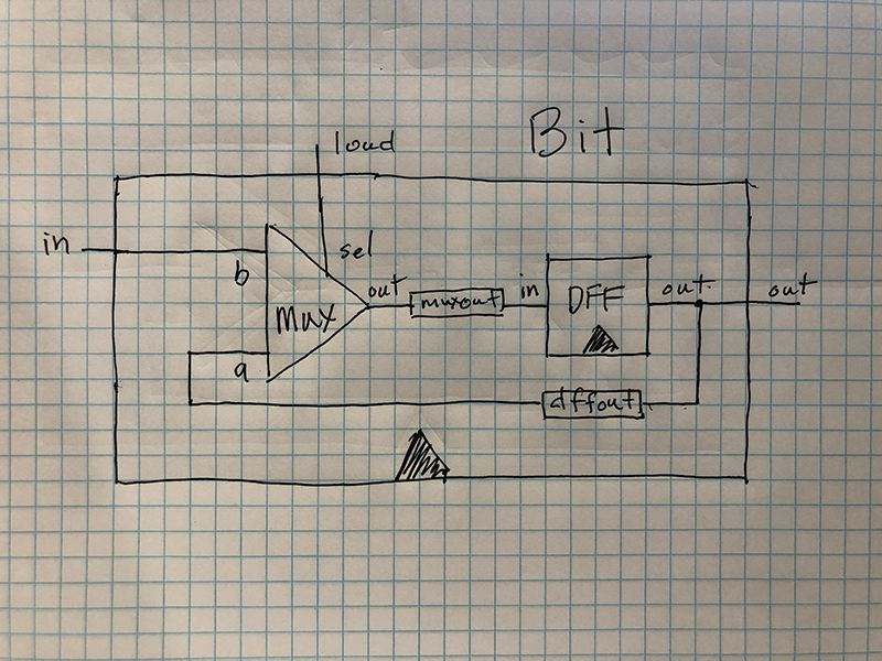
Bit
/**
 * 1-bit register:
 * If load[t] == 1 then out[t+1] = in[t]
 *                 else out does not change (out[t+1] = out[t])
 */

CHIP Bit {
    IN in, load;
    OUT out;

    PARTS:
    Mux(a=dffout, b=in, sel=load, out=muxout);
    DFF(in=muxout, out=dffout, out=out);
}
Register
/**
 * 16-bit register:
 * If load[t] == 1 then out[t+1] = in[t]
 * else out does not change
 */

CHIP Register {
    IN in[16], load;
    OUT out[16];

    PARTS:
    Bit(in=in[0], load=load, out=out[0]);
    Bit(in=in[1], load=load, out=out[1]);
    Bit(in=in[2], load=load, out=out[2]);
    Bit(in=in[3], load=load, out=out[3]);
    Bit(in=in[4], load=load, out=out[4]);
    Bit(in=in[5], load=load, out=out[5]);
    Bit(in=in[6], load=load, out=out[6]);
    Bit(in=in[7], load=load, out=out[7]);
    Bit(in=in[8], load=load, out=out[8]);
    Bit(in=in[9], load=load, out=out[9]);
    Bit(in=in[10], load=load, out=out[10]);
    Bit(in=in[11], load=load, out=out[11]);
    Bit(in=in[12], load=load, out=out[12]);
    Bit(in=in[13], load=load, out=out[13]);
    Bit(in=in[14], load=load, out=out[14]);
    Bit(in=in[15], load=load, out=out[15]);
}
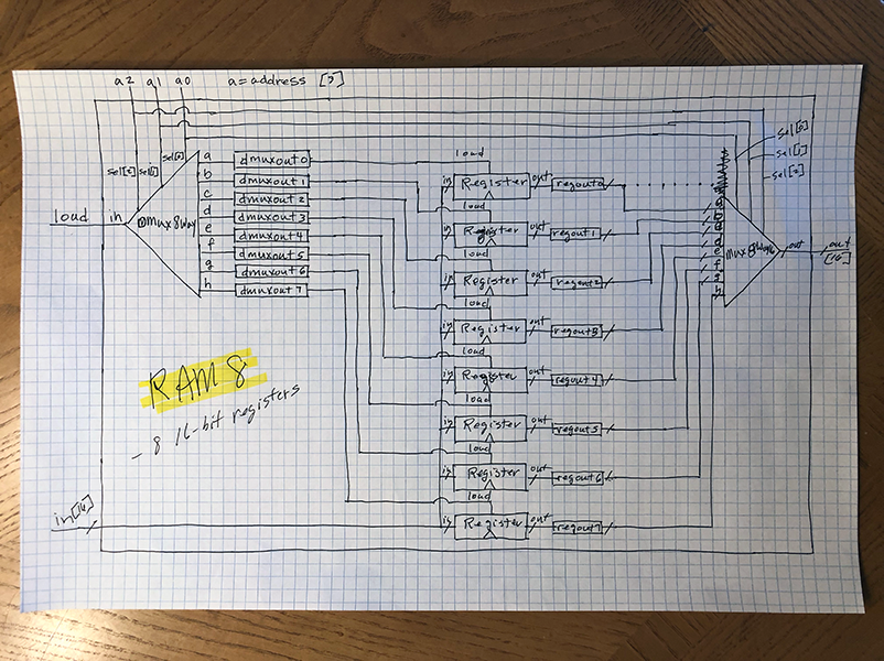
RAM8
/**
 * Memory of 8 registers, each 16 bit-wide. Out holds the value
 * stored at the memory location specified by address. If load==1, then
 * the in value is loaded into the memory location specified by address
 * (the loaded value will be emitted to out from the next time step onward).
 */

CHIP RAM8 {
    IN in[16], load, address[3];
    OUT out[16];

    PARTS:
    DMux8Way(
        in=load,
        sel[2]=address[2],
        sel[1]=address[1],
        sel[0]=address[0],
        a=dmuxout0,
        b=dmuxout1,
        c=dmuxout2,
        d=dmuxout3,
        e=dmuxout4,
        f=dmuxout5,
        g=dmuxout6,
        h=dmuxout7);
    Register(in=in, load=dmuxout0, out=regout0);
    Register(in=in, load=dmuxout1, out=regout1);
    Register(in=in, load=dmuxout2, out=regout2);
    Register(in=in, load=dmuxout3, out=regout3);
    Register(in=in, load=dmuxout4, out=regout4);
    Register(in=in, load=dmuxout5, out=regout5);
    Register(in=in, load=dmuxout6, out=regout6);
    Register(in=in, load=dmuxout7, out=regout7);
    Mux8Way16(
        a=regout0,
        b=regout1,
        c=regout2,
        d=regout3,
        e=regout4,
        f=regout5,
        g=regout6,
        h=regout7,
        sel[2]=address[2],
        sel[1]=address[1],
        sel[0]=address[0],
        out=out);
}
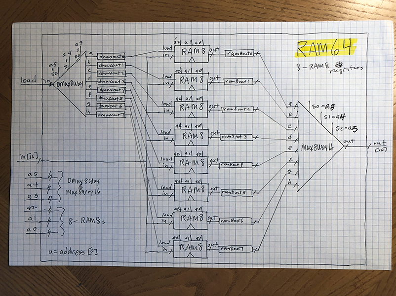
RAM64
/**
 * Memory of 64 registers, each 16 bit-wide. Out holds the value
 * stored at the memory location specified by address. If load==1, then
 * the in value is loaded into the memory location specified by address
 * (the loaded value will be emitted to out from the next time step onward).
 */

CHIP RAM64 {
    IN in[16], load, address[6];
    OUT out[16];

    PARTS:
    DMux8Way(
        in=load,
        sel[2]=address[5],
        sel[1]=address[4],
        sel[0]=address[3],
        a=dmuxout0,
        b=dmuxout1,
        c=dmuxout2,
        d=dmuxout3,
        e=dmuxout4,
        f=dmuxout5,
        g=dmuxout6,
        h=dmuxout7);
    RAM8(
        in=in,
        load=dmuxout0,
        address[2]=address[2],
        address[1]=address[1],
        address[0]=address[0],
        out=ram8out0);
    RAM8(
        in=in,
        load=dmuxout1,
        address[2]=address[2],
        address[1]=address[1],
        address[0]=address[0],
        out=ram8out1);
    RAM8(
        in=in,
        load=dmuxout2,
        address[2]=address[2],
        address[1]=address[1],
        address[0]=address[0],
        out=ram8out2);
    RAM8(
        in=in,
        load=dmuxout3,
        address[2]=address[2],
        address[1]=address[1],
        address[0]=address[0],
        out=ram8out3);
    RAM8(
        in=in,
        load=dmuxout4,
        address[2]=address[2],
        address[1]=address[1],
        address[0]=address[0],
        out=ram8out4);
    RAM8(
        in=in,
        load=dmuxout5,
        address[2]=address[2],
        address[1]=address[1],
        address[0]=address[0],
        out=ram8out5);
    RAM8(
        in=in,
        load=dmuxout6,
        address[2]=address[2],
        address[1]=address[1],
        address[0]=address[0],
        out=ram8out6);
    RAM8(
        in=in,
        load=dmuxout7,
        address[2]=address[2],
        address[1]=address[1],
        address[0]=address[0],
        out=ram8out7);
    Mux8Way16(
        a=ram8out0,
        b=ram8out1,
        c=ram8out2,
        d=ram8out3,
        e=ram8out4,
        f=ram8out5,
        g=ram8out6,
        h=ram8out7,
        sel[2]=address[5],
        sel[1]=address[4],
        sel[0]=address[3],
        out=out);
}
RAM512
/**
 * Memory of 512 registers, each 16 bit-wide. Out holds the value
 * stored at the memory location specified by address. If load==1, then
 * the in value is loaded into the memory location specified by address
 * (the loaded value will be emitted to out from the next time step onward).
 */

CHIP RAM512 {
    IN in[16], load, address[9];
    OUT out[16];

    PARTS:
    DMux8Way(
        in=load,
        sel[2]=address[8],
        sel[1]=address[7],
        sel[0]=address[6],
        a=dmuxout0,
        b=dmuxout1,
        c=dmuxout2,
        d=dmuxout3,
        e=dmuxout4,
        f=dmuxout5,
        g=dmuxout6,
        h=dmuxout7);
    RAM64(
        in=in,
        load=dmuxout0,
        address[5]=address[5],
        address[4]=address[4],
        address[3]=address[3],
        address[2]=address[2],
        address[1]=address[1],
        address[0]=address[0],
        out=ram64out0);
    RAM64(
        in=in,
        load=dmuxout1,
        address[5]=address[5],
        address[4]=address[4],
        address[3]=address[3],
        address[2]=address[2],
        address[1]=address[1],
        address[0]=address[0],
        out=ram64out1);
    RAM64(
        in=in,
        load=dmuxout2,
        address[5]=address[5],
        address[4]=address[4],
        address[3]=address[3],
        address[2]=address[2],
        address[1]=address[1],
        address[0]=address[0],
        out=ram64out2);
    RAM64(
        in=in,
        load=dmuxout3,
        address[5]=address[5],
        address[4]=address[4],
        address[3]=address[3],
        address[2]=address[2],
        address[1]=address[1],
        address[0]=address[0],
        out=ram64out3);
    RAM64(
        in=in,
        load=dmuxout4,
        address[5]=address[5],
        address[4]=address[4],
        address[3]=address[3],
        address[2]=address[2],
        address[1]=address[1],
        address[0]=address[0],
        out=ram64out4);
    RAM64(
        in=in,
        load=dmuxout5,
        address[5]=address[5],
        address[4]=address[4],
        address[3]=address[3],
        address[2]=address[2],
        address[1]=address[1],
        address[0]=address[0],
        out=ram64out5);
    RAM64(
        in=in,
        load=dmuxout6,
        address[5]=address[5],
        address[4]=address[4],
        address[3]=address[3],
        address[2]=address[2],
        address[1]=address[1],
        address[0]=address[0],
        out=ram64out6);
    RAM64(
        in=in,
        load=dmuxout7,
        address[5]=address[5],
        address[4]=address[4],
        address[3]=address[3],
        address[2]=address[2],
        address[1]=address[1],
        address[0]=address[0],
        out=ram64out7);
    Mux8Way16(
        a=ram64out0,
        b=ram64out1,
        c=ram64out2,
        d=ram64out3,
        e=ram64out4,
        f=ram64out5,
        g=ram64out6,
        h=ram64out7,
        sel[2]=address[8],
        sel[1]=address[7],
        sel[0]=address[6],
        out=out);
}
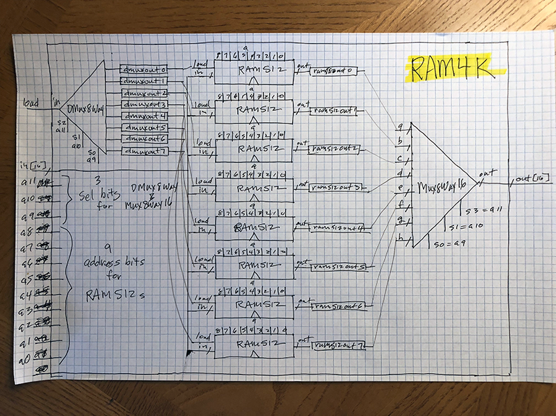
RAM4K
/**
 * Memory of 4K registers, each 16 bit-wide. Out holds the value
 * stored at the memory location specified by address. If load==1, then
 * the in value is loaded into the memory location specified by address
 * (the loaded value will be emitted to out from the next time step onward).
 */

CHIP RAM4K {
    IN in[16], load, address[12];
    OUT out[16];

    PARTS:
    DMux8Way(
        in=load,
        sel[2]=address[11],
        sel[1]=address[10],
        sel[0]=address[9],
        a=dmuxout0,
        b=dmuxout1,
        c=dmuxout2,
        d=dmuxout3,
        e=dmuxout4,
        f=dmuxout5,
        g=dmuxout6,
        h=dmuxout7);
    RAM512(
        in=in,
        load=dmuxout0,
        address[8]=address[8],
        address[7]=address[7],
        address[6]=address[6],
        address[5]=address[5],
        address[4]=address[4],
        address[3]=address[3],
        address[2]=address[2],
        address[1]=address[1],
        address[0]=address[0],
        out=ram512out0);
    RAM512(
        in=in,
        load=dmuxout1,
        address[8]=address[8],
        address[7]=address[7],
        address[6]=address[6],
        address[5]=address[5],
        address[4]=address[4],
        address[3]=address[3],
        address[2]=address[2],
        address[1]=address[1],
        address[0]=address[0],
        out=ram512out1);
    RAM512(
        in=in,
        load=dmuxout2,
        address[8]=address[8],
        address[7]=address[7],
        address[6]=address[6],
        address[5]=address[5],
        address[4]=address[4],
        address[3]=address[3],
        address[2]=address[2],
        address[1]=address[1],
        address[0]=address[0],
        out=ram512out2);
    RAM512(
        in=in,
        load=dmuxout3,
        address[8]=address[8],
        address[7]=address[7],
        address[6]=address[6],
        address[5]=address[5],
        address[4]=address[4],
        address[3]=address[3],
        address[2]=address[2],
        address[1]=address[1],
        address[0]=address[0],
        out=ram512out3);
    RAM512(
        in=in,
        load=dmuxout4,
        address[8]=address[8],
        address[7]=address[7],
        address[6]=address[6],
        address[5]=address[5],
        address[4]=address[4],
        address[3]=address[3],
        address[2]=address[2],
        address[1]=address[1],
        address[0]=address[0],
        out=ram512out4);
    RAM512(
        in=in,
        load=dmuxout5,
        address[8]=address[8],
        address[7]=address[7],
        address[6]=address[6],
        address[5]=address[5],
        address[4]=address[4],
        address[3]=address[3],
        address[2]=address[2],
        address[1]=address[1],
        address[0]=address[0],
        out=ram512out5);
    RAM512(
        in=in,
        load=dmuxout6,
        address[8]=address[8],
        address[7]=address[7],
        address[6]=address[6],
        address[5]=address[5],
        address[4]=address[4],
        address[3]=address[3],
        address[2]=address[2],
        address[1]=address[1],
        address[0]=address[0],
        out=ram512out6);
    RAM512(
        in=in,
        load=dmuxout7,
        address[8]=address[8],
        address[7]=address[7],
        address[6]=address[6],
        address[5]=address[5],
        address[4]=address[4],
        address[3]=address[3],
        address[2]=address[2],
        address[1]=address[1],
        address[0]=address[0],
        out=ram512out7);
    Mux8Way16(
        a=ram512out0,
        b=ram512out1,
        c=ram512out2,
        d=ram512out3,
        e=ram512out4,
        f=ram512out5,
        g=ram512out6,
        h=ram512out7,
        sel[2]=address[11],
        sel[1]=address[10],
        sel[0]=address[9],
        out=out);
}
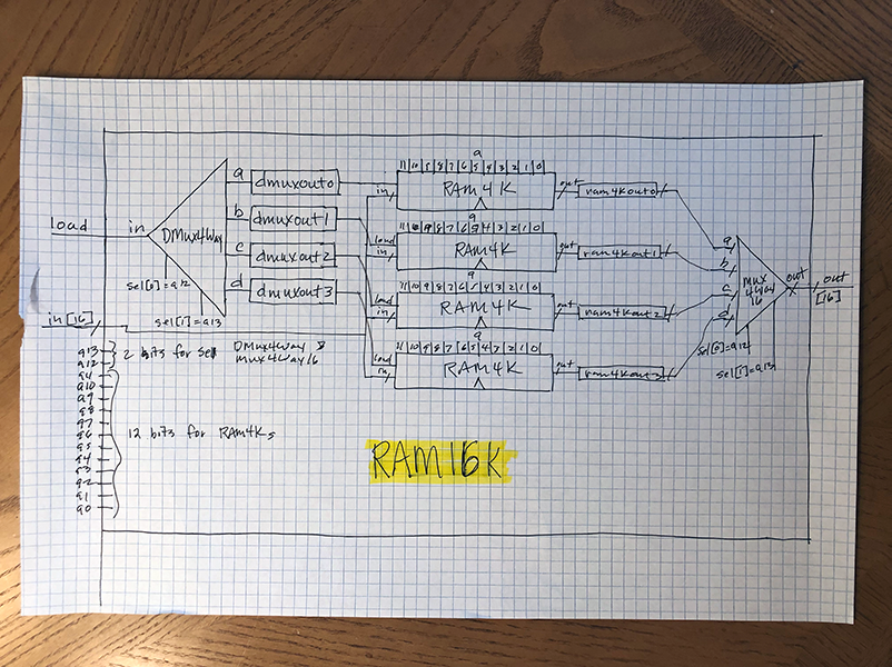
RAM16K
/**
 * Memory of 16K registers, each 16 bit-wide. Out holds the value
 * stored at the memory location specified by address. If load==1, then
 * the in value is loaded into the memory location specified by address
 * (the loaded value will be emitted to out from the next time step onward).
 */

CHIP RAM16K {
    IN in[16], load, address[14];
    OUT out[16];

    PARTS:
    DMux4Way(
        in=load,
        sel[1]=address[13],
        sel[0]=address[12],
        a=dmuxout0,
        b=dmuxout1,
        c=dmuxout2,
        d=dmuxout3);
    RAM4K(
        in=in,
        load=dmuxout0,
        address[11]=address[11],
        address[10]=address[10],
        address[9]=address[9],
        address[8]=address[8],
        address[7]=address[7],
        address[6]=address[6],
        address[5]=address[5],
        address[4]=address[4],
        address[3]=address[3],
        address[2]=address[2],
        address[1]=address[1],
        address[0]=address[0],
        out=ram4kout0);
    RAM4K(
        in=in,
        load=dmuxout1,
        address[11]=address[11],
        address[10]=address[10],
        address[9]=address[9],
        address[8]=address[8],
        address[7]=address[7],
        address[6]=address[6],
        address[5]=address[5],
        address[4]=address[4],
        address[3]=address[3],
        address[2]=address[2],
        address[1]=address[1],
        address[0]=address[0],
        out=ram4kout1);
    RAM4K(
        in=in,
        load=dmuxout2,
        address[11]=address[11],
        address[10]=address[10],
        address[9]=address[9],
        address[8]=address[8],
        address[7]=address[7],
        address[6]=address[6],
        address[5]=address[5],
        address[4]=address[4],
        address[3]=address[3],
        address[2]=address[2],
        address[1]=address[1],
        address[0]=address[0],
        out=ram4kout2);
    RAM4K(
        in=in,
        load=dmuxout3,
        address[11]=address[11],
        address[10]=address[10],
        address[9]=address[9],
        address[8]=address[8],
        address[7]=address[7],
        address[6]=address[6],
        address[5]=address[5],
        address[4]=address[4],
        address[3]=address[3],
        address[2]=address[2],
        address[1]=address[1],
        address[0]=address[0],
        out=ram4kout3);
    Mux4Way16(
        a=ram4kout0,
        b=ram4kout1,
        c=ram4kout2,
        d=ram4kout3,
        sel[1]=address[13],
        sel[0]=address[12],
        out=out);
}
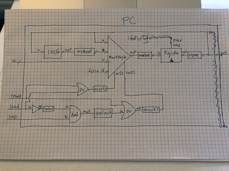
PC
/**
 * A 16-bit counter with load and reset control bits.
 * if      (reset[t] == 1) out[t+1] = 0
 * else if (load[t] == 1)  out[t+1] = in[t]
 * else if (inc[t] == 1)   out[t+1] = out[t] + 1  (integer addition)
 * else                    out[t+1] = out[t]
 */

CHIP PC {
    IN in[16],load,inc,reset;
    OUT out[16];

    PARTS:
    Inc16(
        in=regout,
        out=inc16out);
    Or( // sel[1]
        a=reset,
        b=load,
        out=orout0);
    Or( // sel[0]
        a=reset,
        b=andout,
        out=orout1);
    Not(
        in=load,
        out=notout);
    And(
        a=notout,
        b=inc,
        out=andout);
    Mux4Way16(
        a=regout,
        b=inc16out,
        c=in,
        d=false,
        sel[1]=orout0,
        sel[0]=orout1,
        out=mux4out);
    Register(
        in=mux4out,
        load=true,
        out=regout,
        out=out);
}
Computer Architecture (3 Chips)
Memory
/**
 * The complete address space of the Hack computer's memory,
 * including RAM and memory-mapped I/O.
 * The chip facilitates read and write operations, as follows:
 *     Read:  out(t) = Memory[address(t)](t)
 *     Write: if load(t-1) then Memory[address(t-1)](t) = in(t-1)
 * In words: the chip always outputs the value stored at the memory
 * location specified by address. If load==1, the in value is loaded
 * into the memory location specified by address. This value becomes
 * available through the out output from the next time step onward.
 * Address space rules:
 * Only the upper 16K+8K+1 words of the Memory chip are used.
 * Access to address>0x6000 is invalid. Access to any address in
 * the range 0x4000-0x5FFF results in accessing the screen memory
 * map. Access to address 0x6000 results in accessing the keyboard
 * memory map. The behavior in these addresses is described in the
 * Screen and Keyboard chip specifications given in the book.
 */

CHIP Memory {
    IN in[16], load, address[15];
    OUT out[16];

    PARTS:

// From builtInChips:

    RAM16K(
        in=in,
        load=dmout0,
        address[0]=address[0],
        address[1]=address[1],
        address[2]=address[2],
        address[3]=address[3],
        address[4]=address[4],
        address[5]=address[5],
        address[6]=address[6],
        address[7]=address[7],
        address[8]=address[8],
        address[9]=address[9],
        address[10]=address[10],
        address[11]=address[11],
        address[12]=address[12],
        address[13]=address[13],
        out=ramout);

// From builtInChips:

    Screen(
        in=in,
        load=dmout1,
        address[0]=address[0],
        address[1]=address[1],
        address[2]=address[2],
        address[3]=address[3],
        address[4]=address[4],
        address[5]=address[5],
        address[6]=address[6],
        address[7]=address[7],
        address[8]=address[8],
        address[9]=address[9],
        address[10]=address[10],
        address[11]=address[11],
        address[12]=address[12],
        out=scrout);

// From builtInChips:

    Keyboard(
        out=keyout);

// My implementations:

    DMux(
        in=load,
        sel=address[14],
        a=dmout0,
        b=dmout1);

    Mux4Way16(
        a=ramout,
        b=ramout,
        c=scrout,
        d=keyout,
        sel[0]=address[13],
        sel[1]=address[14],
        out=out);
}
CPU
/**
 * The Hack CPU (Central Processing unit), consisting of an ALU,
 * two registers named A and D, and a program counter named PC.
 * The CPU is designed to fetch and execute instructions written in
 * the Hack machine language. In particular, functions as follows:
 * Executes the inputted instruction according to the Hack machine
 * language specification. The D and A in the language specification
 * refer to CPU-resident registers, while M refers to the external
 * memory location addressed by A, i.e. to Memory[A]. The inM input
 * holds the value of this location. If the current instruction needs
 * to write a value to M, the value is placed in outM, the address
 * of the target location is placed in the addressM output, and the
 * writeM control bit is asserted. (When writeM==0, any value may
 * appear in outM). The outM and writeM outputs are combinational:
 * they are affected instantaneously by the execution of the current
 * instruction. The addressM and pc outputs are clocked: although they
 * are affected by the execution of the current instruction, they commit
 * to their new values only in the next time step. If reset==1 then the
 * CPU jumps to address 0 (i.e. pc is set to 0 in next time step) rather
 * than to the address resulting from executing the current instruction.
 */

CHIP CPU {

    IN  inM[16],         // M value input  (M = contents of RAM[A])
        instruction[16], // Instruction for execution
        reset;           // Signals whether to re-start the current
                         // program (reset==1) or continue executing
                         // the current program (reset==0).

    OUT outM[16],        // M value output
        writeM,          // Write to M?
        addressM[15],    // Address in data memory (of M)
        pc[15];          // address of next instruction

    PARTS:

    ALU(
        x=dregout,   // D
        y=muxamout,  // A/M
        zx=c1out,    // C1
        nx=c2out,    // C2
        zy=c3out,    // C3
        ny=c4out,    // C4
        f=c5out,     // C5
        no=c6out,    // C6
        out=aluout,  // DReg, AReg
        out=outM,
        zr=zrout,
        ng=ngout);

    ARegister(
        in=muxinstout,
        load=aregload,
        out=aregout,
        out[0]=addressM[0],
        out[1]=addressM[1],
        out[2]=addressM[2],
        out[3]=addressM[3],
        out[4]=addressM[4],
        out[5]=addressM[5],
        out[6]=addressM[6],
        out[7]=addressM[7],
        out[8]=addressM[8],
        out[9]=addressM[9],
        out[10]=addressM[10],
        out[11]=addressM[11],
        out[12]=addressM[12],
        out[13]=addressM[13],
        out[14]=addressM[14],
        out[15]=false);

    DRegister(in=aluout, load=dregload, out=dregout);

// Instruction > AReg

    Mux16(a=instruction, b=aluout, sel=instruction[15], out=muxinstout);

// A/M > ALU

    Mux16(a=aregout, b=inM, sel=instruction[12], out=muxamout);

// Control: dest

// A Reg
    Not(in=instruction[15], out=aregloadnot);
    And(a=instruction[15], b=instruction[5], out=aregloadand);
    Or(a=aregloadnot, b=aregloadand, out=aregload);

// D Reg

    And(a=instruction[15], b=instruction[4], out=dregload);

// M Reg

    And(a=instruction[15], b=instruction[3], out=writeM);

// Control: c1 through c6

    And(a=instruction[15], b=instruction[11], out=c1out);  // c1 = zx = instruction[11]
    And(a=instruction[15], b=instruction[10], out=c2out);  // c2 = nx = instruction[10]
    And(a=instruction[15], b=instruction[09], out=c3out);  // c3 = zy = instruction[09]
    And(a=instruction[15], b=instruction[08], out=c4out);  // c4 = ny = instruction[08]
    And(a=instruction[15], b=instruction[07], out=c5out);  // c5 =  f = instruction[07]
    And(a=instruction[15], b=instruction[06], out=c6out);  // c6 = no = instruction[06]

// Control: jump

// Necessary Not gates

    Not(in=instruction[2], out=nj1); // j1
    Not(in=instruction[1], out=nj2); // j2
    Not(in=instruction[0], out=nj3); // j3
    Not(in=zrout, out=nzr);          // zr
    Not(in=ngout, out=nng);          // ng

// Flags

    And(a=zrout, b=nng, out=feq); // =
    And(a=nzr, b=ngout, out=flt); // <
    And(a=nzr, b=nng, out=fgt);   // >

// JMP

    And(a=instruction[2], b=instruction[1], out=jmp);
    And(a=jmp, b=instruction[0], out=jmpout);

// JEQ

    And(a=nj1, b=instruction[1], out=jeq0);
    And(a=jeq0, b=nj3, out=jeq1);
    And(a=jeq1, b=feq, out=jeqout);

// JLT

    And(a=instruction[2], b=nj2, out=jlt0);
    And(a=jlt0, b=nj3, out=jlt1);
    And(a=jlt1, b=flt, out=jltout);

// JGT

    And(a=nj1, b=nj2, out=jgt0);
    And(a=jgt0, b=instruction[0], out=jgt1);
    And(a=jgt1, b=fgt, out=jgtout);

// JGE

    Or(a=fgt, b=feq, out=orjgeout);

    And(a=nj1, b=instruction[1], out=jge0);
    And(a=jge0, b=instruction[0], out=jge1);
    And(a=jge1, b=orjgeout, out=jgeout);

// JLE

    Or(a=flt, b=feq, out=orjleout);

    And(a=instruction[2], b=instruction[1], out=jle0);
    And(a=jle0, b=nj3, out=jle1);
    And(a=jle1, b=orjleout, out=jleout);

// JNE

    And(a=instruction[2], b=nj2, out=jne0);
    And(a=jne0, b=instruction[0], out=jne1);
    And(a=jne1, b=nzr, out=jneout);

// Or8Way > load

    Or8Way(
        in[0]=jeqout,  // JEQ
        in[1]=jltout,  // JLT
        in[2]=jgtout,  // JGT
        in[3]=jgeout,  // JGE
        in[4]=jleout,  // JLE
        in[5]=jneout,  // JNE
        in[6]=jmpout,  // JMP
        in[7]=false,
        out=or8wayout);

// Make sure C-instruction & jump = 1

    And(a=or8wayout, b=instruction[15], out=loadin);

// Invert for inc bit: if load=1 then inc=0, if load=0 then inc=1

    Not(in=loadin, out=incin);

// PC

    PC(
        in=aregout,
        load=loadin,
        inc=incin,
        reset=reset,
        out[0]=pc[0],
        out[1]=pc[1],
        out[2]=pc[2],
        out[3]=pc[3],
        out[4]=pc[4],
        out[5]=pc[5],
        out[6]=pc[6],
        out[7]=pc[7],
        out[8]=pc[8],
        out[9]=pc[9],
        out[10]=pc[10],
        out[11]=pc[11],
        out[12]=pc[12],
        out[13]=pc[13],
        out[14]=pc[14],
        out[15]=false);
}
Computer
The only chip that is not in the “THe Hack Chip Set API.md” file. Because this is the end of the API; the computer is not used as a “part” in the N2T project. That’s what there are 38 chips here and 37 in “The Hack Chip Set API.md”.
/**
 * The HACK computer, including CPU, ROM and RAM.
 * When reset is 0, the program stored in the computer's ROM executes.
 * When reset is 1, the execution of the program restarts.
 * Thus, to start a program's execution, reset must be pushed "up" (1)
 * and "down" (0). From this point onward the user is at the mercy of
 * the software. In particular, depending on the program's code, the
 * screen may show some output and the user may be able to interact
 * with the computer via the keyboard.
 */

CHIP Computer {

    IN reset;

    PARTS:

// My implementation:

    CPU(
        inM=memoryout,
        instruction=rom32kout,
        reset=reset,
        outM=outMout,
        writeM=writeMout,
        addressM=addressMout,
        pc=pcout);

// From builtInChips:

    ROM32K(
        address=pcout,
        out=rom32kout);

// From builtInChips:

    Memory(
        in=outMout,
        load=writeMout,
        address=addressMout,
        out=memoryout);
}